Here is the latest version of the One Servo Walker in action! He can turn as well as walk straight. (It looks pretty aggressive when he turns…)
The design has been refined to make him walk better, and to make him easier for others to build and recreate.
Like the earlier version, the One Servo Walker is a 3D-printed robot that can “walk” using a single servo.
The main updates in this version are the front guard, which keep to guide the legs, and the rear “carriage”, which has been lengthened to make him balance better.
As shown in the video, he can move forward as well as steer left and right. I’ll be refining the software to make him easier to control/steer.
For now, he has no sensors, and I’ve just programmed him to walk and turn at pre-set intervals. He needs sensors! I’m planning to add 2 light sensors so that he can follow light sources (or maybe follow a line on the ground), and maybe add a distance sensor so that he can explore and avoid obstacles.
How does this robot walk with a single servo? Bascially, moving the servo from side to side will cause this robot to move forward. And having the servo move only to one side will cause the robot to turn! It is able to do this thanks to the awesome passive leg design by erco. (Check out the bot that inspired the One Servo Walker here: https://www.youtube.com/watch?v=4CaAq6gQbLY)
Building the One Servo Walker
Let’s look at this build in more details!
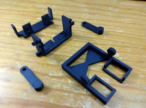
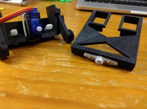
Here are the 5 3D-printed parts. You can download the STL files from Thingiverse here: http://www.thingiverse.com/thing:1080284
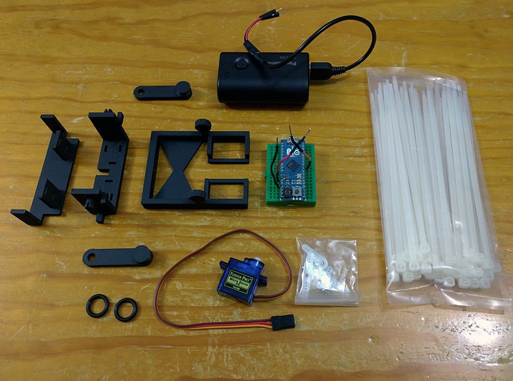
And here is the complete set of parts used in this build.
It consists of:
- The 5 3D-printed parts
- 2 small O-rings
- 1 9g Micro Servo (and its screws and servo horn)
- 1 Mobile phone booster battery
- 1 hacked USB cable that we can use as a power cable
- 1 Arduino Micro on a small breadboard
- 3 zip ties
Here are the assembly steps!
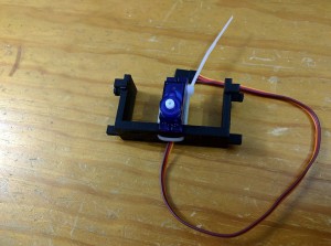
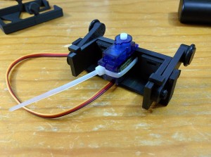
1. Attach the Servo to the Front Body
Secure it with a zip tie.
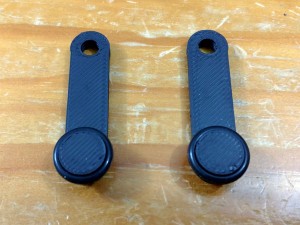
2. Attach the O-Rings to the Legs
Super easy! 🙂
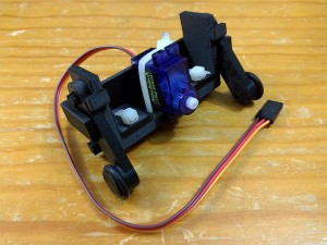
3. Attach the Legs to the Front Body
They just snap onto the pegs!
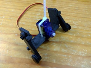
4. Attach the Front Guard
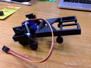
It fits like this, and it is secured into position using 2 zip ties.
5. Attach a Servo Horn onto the Rear Body
There are holes in the rear body for the screws.
6. Attach the Front and Back body sections
Secure using the screw that goes into the servo axel.
You are done!
Electronics and Programming
You are free to use whatever controller you want! If you are super cool, you might even skip a microcontroller altogether and use a Timer 555. (That is too cool for me… Some day I’d like to do that.)
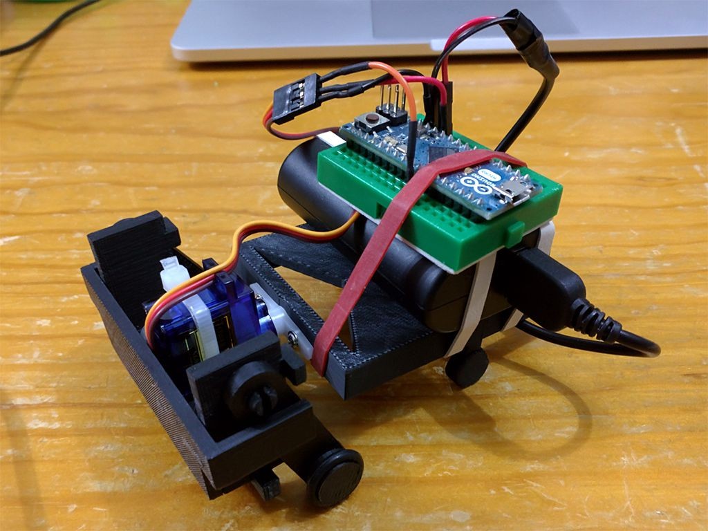
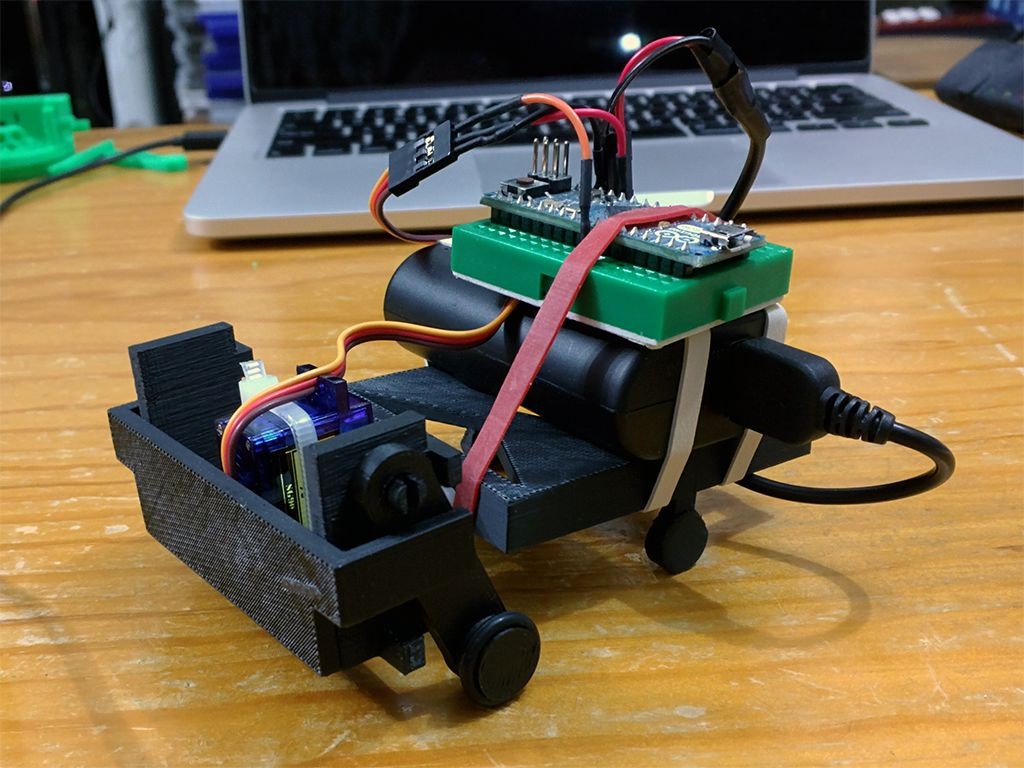
In my current build, I’m using an Arduino Micro on a tiny breadboard. And I’m powering everything using a Phone Booster Battery. I’ve just attached everything using a rubber band (for now).
Getting him to walk forward is very easy. Just have the servo oscillate back and forth evenly!
To get him to turn, you need to be a bit trickier… Essentially, turning involves making the oscillations lop-sided so that he only pushes with one leg during the turn.
I found that just changing the turn angles didn’t always make him turn!! What I discovered was that changing the speed of the movements and using some sharp downward swings was a big help in getting him to turn “assertively”. In my tests, I found that swinging too gently during turns would sometimes make him strafe or not turn at all. (Strafing was actually quite cool and I might see if I can reproduce it on purpose.)
Also, note that how you distribute the weight on his back has some effect on movement. So, don’t just glue everything down before you have him walking. Have a play first!
I found that putting the majority of the weight right on the back legs kept him fairly stable. I will refine/update the rear body design as I figure this guy out more!
Haha. So, even though he’s a simple bot to build, there was a lot to figure out! It took me a while to get him to move like I wanted. And, there’s still more to figure out… I’m going to continue refining the code to get smoother control over movement and steering. I’ll share out my version when it’s ready, but have a play yourself, and let me know if you figure out any cool movement techniques. 🙂
Further Work
Here’s my current build.
I say current build because I’m not done yet. I want to add sensors to him. Also, I may switch the microcontroller to a Bluno so that I can add Bluetooth Control via a phone app (similar to MobBob).
Also, as you can see from the build instructions… the rear body is really just a carriage for holding the parts. It does need to be there to keep the robot balanced, but its design can be customized to your needs. For example, you may redesign it specifically for your battery and controller.
I have a bunch of ideas for the rear body that I still want to play with! I’m thinking:
- A fully enclosed shell to hold the electronics
- A version with rear caster legs to make movement smoother
- A solar panel on the back to charge his battery when I’m not using him
- A carriage big enough to carry a phone (on its back) so that I can make use of the phone’s other sensors and features. I’m keen to use the phone’s gyro to get more precise steering control, and the phone microphone/speaker will be great for making this robot more interactive. (Yep. Voice control!)
Also as much of the body is “passive”… I have some crazy ideas for making a version that can fold up and be put into your pocket. Hehe. Before I do that, I should get some sensors onto this version, and work on the software so that he has more functionality.

can use another DC motor
please sir reply
You could probably use a DC motor… but it’ll be tricky to control to get it to move back and forth like that. If you were planning to use a DC motor, perhaps consider some sort of gearing mechanism to convert the spinning motion into a back and forth motion.
can I have the source code please